


Which Electrode Suits Gas Burners in OEM Design?
A burner may produce a visible spark during bench testing and still fail to ignite consistently once it enters a hot, humid, grease-exposed appliance. For OEM teams asking which electrode suits gas burners, the answer is not a single catalog part. The correct choice depends on burner architecture, ignition voltage, fuel type, operating environment, safety requirements, and manufacturing tolerances.
An ignition electrode is a small component with a direct influence on appliance reliability, service rates, and perceived product quality. Its job is straightforward: create a controlled spark at the burner head. Engineering it correctly is less simple. The electrode must maintain electrical insulation, resist thermal cycling, preserve the spark gap, and fit the mechanical and electronic design of the complete ignition system.
Which Electrode Suits Gas Burners? Start With the Application
The first decision is whether the electrode is intended only for spark ignition or must also support flame sensing. Spark-only electrodes are common in systems using a separate thermocouple, thermopile, or flame sensor. Combination designs can reduce component count when the ignition rod also serves as an ionization flame-sensing probe, but they require careful coordination with the control module.
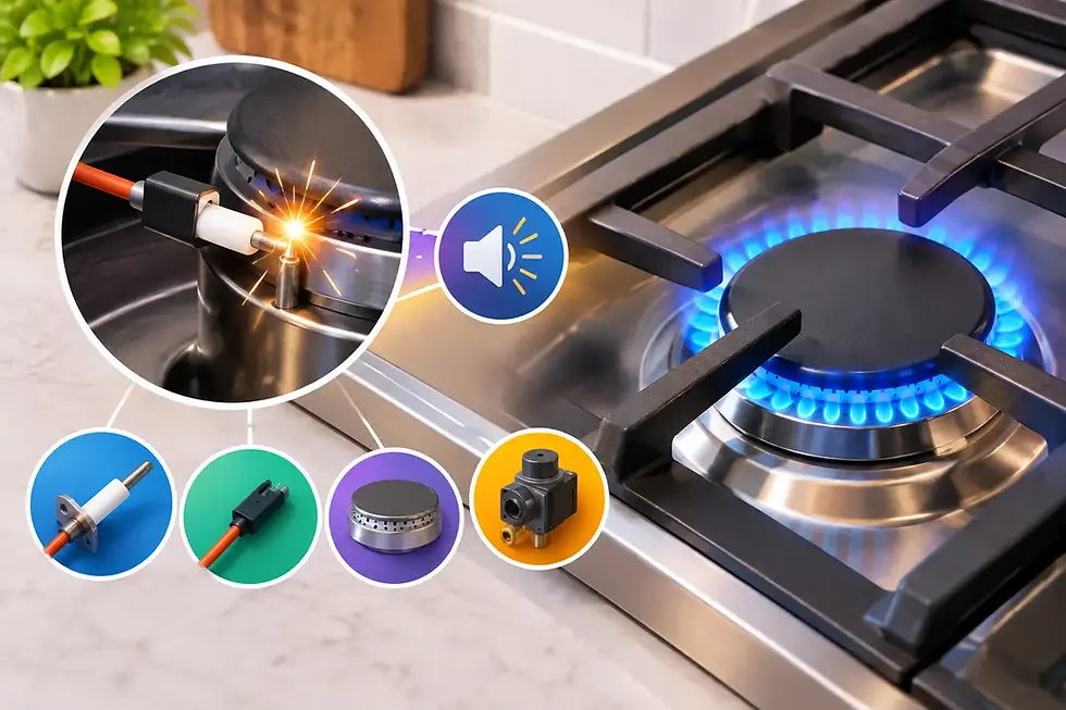
For spark ignition, the electrode receives a high-voltage pulse from an ignition module. The spark jumps from the electrode tip to a grounded burner surface, igniting the gas-air mixture. The required voltage varies with the electrode gap, burner geometry, contamination, humidity, altitude, and fuel composition. A design that sparks easily in clean laboratory conditions may need a higher safety margin in commercial cooking equipment or outdoor appliances.
Flame-sensing electrodes operate differently after ignition. They measure the small ionization current conducted through the flame to verify that combustion is present. In this configuration, insulation quality, electrode positioning, and electrical noise control become especially significant. A poorly located probe can create false flame-loss readings even though the burner is operating.
Electrode Material: Why Nickel Alloys Are Common
The exposed metal rod must tolerate repeated sparking and elevated temperatures without excessive oxidation or erosion. Nickel-based alloys are widely used because they offer a practical balance of conductivity, high-temperature stability, corrosion resistance, and cost. The precise alloy selection should reflect the burner duty cycle and operating temperature.
For residential or light-duty appliances, a standard nickel alloy electrode may be suitable when it is correctly positioned and protected from direct flame impingement. Commercial ranges, industrial heaters, and high-cycle equipment can demand materials with stronger resistance to scaling, thermal fatigue, and surface degradation. If the electrode tip deteriorates, its effective shape changes and the spark may become inconsistent.
The surrounding ceramic insulator is equally important. High-alumina ceramic is commonly selected for its dielectric strength and ability to withstand heat. It must resist cracking from thermal shock while maintaining insulation under moisture, grease, carbon deposits, and cleaning chemicals. The ceramic length and profile should provide adequate creepage distance between the energized conductor and grounded metal components.
Material choice should never be treated as an isolated specification. The performance of the metal tip, ceramic body, terminal connection, lead wire, and ignition module must be evaluated as one electrical system.
Spark Gap and Tip Geometry Drive Ignition Reliability
The spark gap is the distance between the electrode tip and the grounded burner target. It is one of the most influential variables in ignition performance. A gap that is too small may be prone to fouling, arcing to an unintended surface, or inconsistent ignition across production variation. A gap that is too large can exceed the practical output of the ignition module, particularly after contamination or wear develops.
There is no universal spark-gap dimension for every gas burner. The correct gap depends on module voltage, electrode geometry, burner material, gas flow pattern, and available mounting tolerances. The goal is to create a spark in the zone where the gas-air mixture is reliably ignitable, not merely where a spark is easiest to produce.
Tip geometry affects both spark concentration and durability. A shaped or pointed tip can concentrate the electric field and lower the voltage needed to initiate a spark. However, an overly sharp tip can wear or oxidize faster in demanding applications. A rounded tip may last longer but can require different gap and voltage settings. The best geometry balances ignition consistency with expected appliance life.
Positioning matters just as much. The electrode should be close enough to the burner ports to ignite the primary flame promptly, yet far enough from the hottest flame zone to avoid unnecessary thermal stress. It should also be protected from direct exposure to spills, grease runoff, and mechanical damage during cleaning or servicing.
Select Insulation and Mounting for the Real Environment
Many electrode failures are not caused by the spark rod itself. They begin at the ceramic-to-metal interface, mounting bracket, terminal connection, or high-voltage lead. Heat, vibration, cleaning cycles, moisture, and assembly variation can gradually reduce insulation performance.
A well-designed mounting arrangement holds the electrode rigidly so the spark gap does not shift during shipping, installation, or normal appliance use. At the same time, the assembly must account for differential thermal expansion between the burner body, bracket, ceramic, and surrounding enclosure. Excessive clamping force can damage ceramic components. Insufficient support can allow vibration and electrode movement.
For appliances exposed to grease, condensate, or frequent washdown, consider how surface contamination may form a leakage path across the insulator. Longer ceramic paths, shielded mounting locations, and appropriate terminal protection can improve field reliability. In outdoor or high-humidity equipment, moisture resistance and stable high-voltage cable routing require added attention.
The high-voltage lead should be specified as part of the electrode assembly, not as an afterthought. Its insulation rating, connector retention, routing distance from grounded metal, and separation from low-voltage control signals all affect ignition performance and electromagnetic compatibility.
Gas Type, Burner Design, and Altitude Change the Answer
Natural gas and propane do not behave identically at the burner. Their ignition characteristics, air requirements, and burner-orifice designs differ. An electrode that performs well on one fuel configuration may need repositioning or a revised spark gap for another. Dual-fuel or region-specific appliance platforms should be validated with each intended fuel configuration.
Altitude also changes ignition conditions. At higher elevations, lower air density can affect flame propagation and spark breakdown behavior. OEMs building products for broad North American or South American distribution should avoid assuming that sea-level test results represent all installation conditions.
Burner construction creates further variables. Cast burners, stamped steel burners, brass components, and coated surfaces provide different ground paths and physical reference points. Surface coatings or corrosion at the intended ground location can affect spark behavior. The electrode design should identify a stable, repeatable ground target rather than relying on incidental contact through multiple assembled components.
A Practical Specification Checklist for OEM Teams
Before releasing an ignition electrode for production, define the full operating requirement. The most useful specification includes at least these five areas:
Electrical requirements: ignition-module output, expected spark gap, cable length, insulation rating, and any flame-sensing circuit requirements.
Mechanical requirements: mounting method, insertion depth, tip position, assembly tolerances, vibration exposure, and service access.
Thermal and environmental requirements: burner temperature, direct-flame exposure, grease, moisture, cleaning agents, and expected duty cycle.
Burner and fuel conditions: fuel type, burner-port layout, ignition zone, airflow, altitude range, and grounding strategy.
Validation requirements: cold starts, hot restarts, repeated cycling, contamination testing, humidity exposure, vibration, and production-line functional testing.
This information allows an engineering partner to develop an electrode that fits the appliance rather than forcing the appliance to accommodate a generic part. It also reduces late-stage changes to brackets, burner castings, ignition modules, and wiring harnesses.
When a Custom Electrode Is the Better Choice
A standard electrode can be appropriate for mature burner designs with moderate operating demands. Custom development becomes more valuable when an OEM needs a nonstandard ceramic length, specific bend geometry, integrated mounting hardware, special terminal orientation, combination ignition and sensing functionality, or improved resistance to a known field condition.
Custom work is especially useful when ignition issues involve more than the electrode. Repeated failures may reflect a mismatch between module energy, cable routing, burner grounding, and electrode placement. Treating the electrode as one component in a coordinated gas ignition system often identifies improvements that part substitution alone cannot achieve.
Electronica Eltec supports this systems-level approach by combining ignition-electrode development with gas ignition electronics and manufacturable hardware design. For OEM programs, that coordination can simplify validation, improve production consistency, and create a clearer path from prototype testing to long-term supply.
The right electrode is the one that creates a dependable spark at the intended ignition point, survives the appliance environment, and remains stable across normal manufacturing variation. Define those conditions early, validate them under real operating stress, and the ignition system will be far less likely to become the reason a well-designed appliance fails in the field.


Comments