

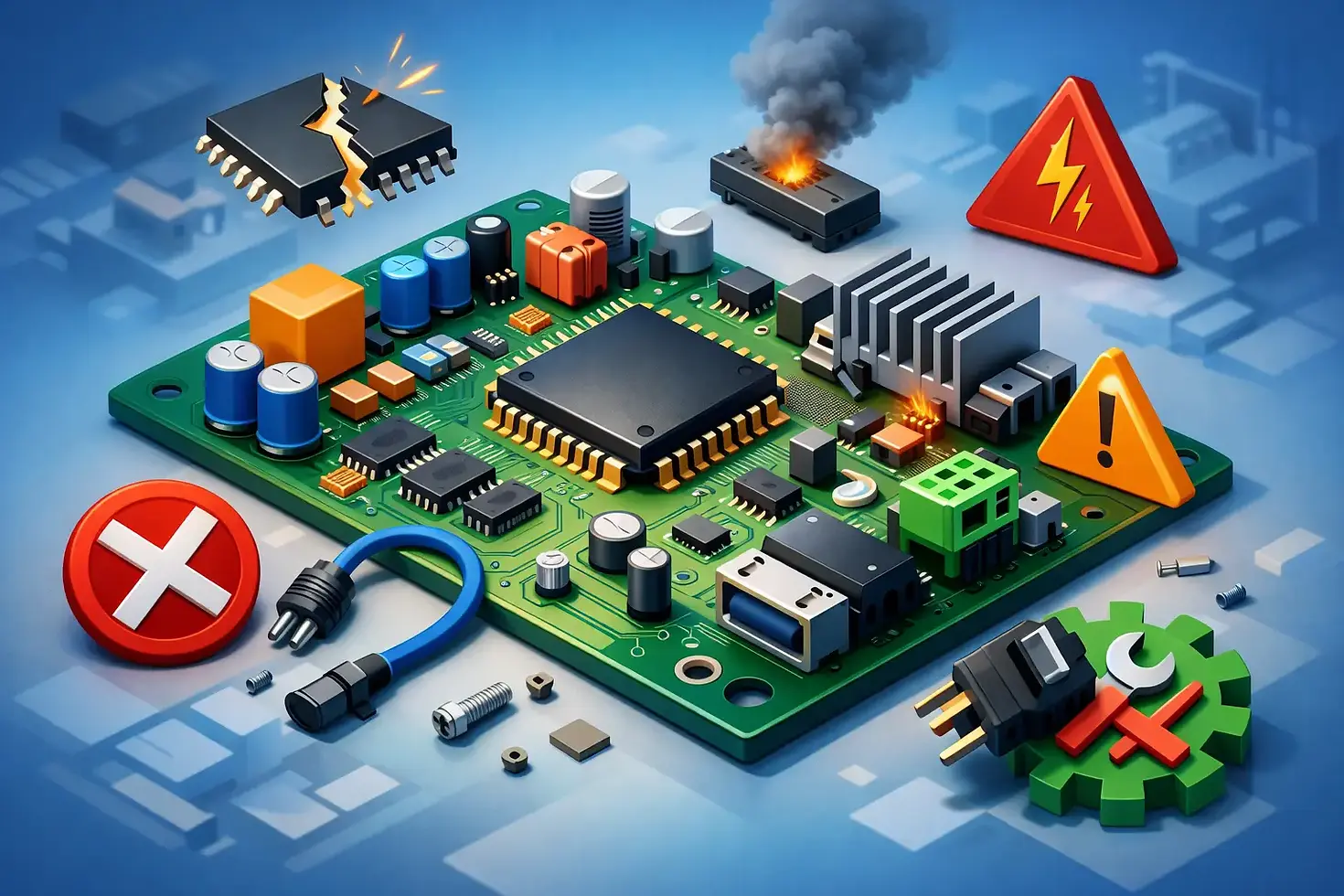
10 Top Industrial Electronics Design Mistakes

A controller can pass a bench test and still fail quickly in the field. Heat, electrical noise, power instability, vibration, installation variation, and service practices expose weaknesses that are easy to miss in a lab. The top industrial electronics design mistakes usually begin much earlier than final testing: they start when product requirements, circuit decisions, enclosure constraints, and manufacturing realities are treated as separate problems.
For OEMs, the cost is not limited to a revised PCB. A weak design can delay a product launch, disrupt a production schedule, increase warranty exposure, and damage confidence in an equipment line. The most effective prevention is to engineer for the complete operating environment and the complete product lifecycle from the beginning.
The top industrial electronics design mistakes that create field risk
1. Designing to nominal conditions instead of real operating conditions
A 24 VDC supply is rarely a perfect 24 VDC supply. Motors start and stop, relays switch, long cable runs add voltage drop, and incoming power can experience surges, transients, or brief interruptions. Designing only around nominal voltage, room temperature, and a clean laboratory load produces margins that may disappear at the customer site.
Requirements should define the full operating envelope: minimum and maximum supply voltage, transient behavior, ambient temperature, humidity, vibration, load characteristics, cable length, and expected operating cycle. For a gas ignition system, that also includes grounding conditions, electrode lead routing, ignition frequency, and the behavior of nearby valves, fans, and control electronics. The right protection strategy depends on the application, but the environment must be understood before components are selected.
2. Treating thermal design as an enclosure problem
Thermal issues are often discovered after the PCB layout is complete and the enclosure has already been specified. By then, the available remedies tend to be expensive: larger heat sinks, higher-rated components, forced airflow, or a redesigned housing.
Temperature rise comes from more than one obvious power device. Regulators, triacs, MOSFETs, relay coils, current-sense elements, and dense control circuitry all contribute. Board copper area, component spacing, vertical mounting, enclosure material, airflow restrictions, and nearby heat sources determine whether that heat can escape. A refrigeration controller and an AC regulator may face very different temperatures, yet both require analysis of worst-case load, elevated ambient conditions, and component derating.
3. Leaving EMC and noise control until compliance testing
Electromagnetic compatibility is not a final-stage checkbox. It is a design discipline that affects schematic architecture, PCB layout, grounding, filtering, cable interfaces, and mechanical integration. When EMC work waits until formal testing, teams may find themselves adding patches that increase cost without fully resolving the root cause.
Industrial equipment must tolerate external disturbances while avoiding emissions that interfere with nearby systems. High-voltage spark generation is a clear example. Spark ignition modules handle fast, high-energy switching events that can couple noise into sensing circuits, communications, power rails, and connected controls. Physical separation, return-current paths, shielding decisions, suppression networks, and connector placement need attention from the first layout review.
4. Underestimating grounding and isolation requirements
A ground symbol on a schematic does not guarantee a safe or quiet system. Functional ground, protective earth, analog reference, digital return, chassis connections, and high-voltage returns each have different purposes. Combining them without a deliberate strategy can create noise problems, unreliable sensing, or unacceptable safety risk.
Isolation requirements should be established from applicable standards, system voltage, installation class, user accessibility, and fault scenarios. Creepage and clearance distances must account for contamination level, materials, altitude where relevant, manufacturing tolerances, and the actual routing of conductors. In ignition applications, high-voltage spacing and controlled discharge paths deserve particular scrutiny. A design that survives a basic functional check may still degrade when moisture, contamination, or assembly variation is introduced.
5. Selecting parts by unit price rather than lifecycle fit
A lower-cost component can raise total product cost when it has limited availability, weak documentation, inconsistent quality history, or inadequate temperature and electrical ratings. This is especially damaging for OEM programs expected to remain in production for years.
Component selection should balance price with qualification status, supply continuity, alternates, lead times, package availability, manufacturer support, and end-of-life risk. It also needs to consider production realities. A part may meet electrical requirements but create placement challenges, require special handling, or complicate test coverage. Design teams should identify approved alternatives early, then validate them where a substitution would affect performance or certification.
6. Building a PCB that works electrically but cannot be manufactured consistently
A prototype can be assembled with extra care and still be unsuitable for repeatable production. Tight clearances, awkward component orientations, insufficient fiducials, untestable nets, poorly defined solder-mask openings, and packages that do not match process capability may not appear until a line is preparing to build at volume.
Design for manufacturability should begin during layout, not at release. Manufacturing engineers need visibility into board stackup, assembly method, panelization, component availability, soldering constraints, inspection access, and programming requirements. This is one reason an integrated engineering and manufacturing partner can reduce development friction: design decisions are reviewed against how the product will actually be built, tested, and serviced.
7. Omitting design-for-test requirements
If the only way to verify a controller is by manually probing it at several points, test time grows, quality becomes operator-dependent, and defects can escape. The issue becomes more costly as production volume rises or product variants multiply.
A practical test strategy defines what must be verified at the board level and at final assembly. That may include power consumption, programming, communications, sensor inputs, output switching, safety interlocks, calibration, and traceability. Test points and interfaces must be accessible without creating unnecessary risk or compromising enclosure integrity. For high-voltage ignition modules, production testing should confirm more than spark presence. It should verify controlled output behavior, correct timing, and safety-relevant functions under defined conditions.
8. Adding connectivity without defining its operating model
Wi-Fi and BLE can create genuine value in industrial and appliance equipment, but connectivity is not simply a module added to an existing controller. Teams must decide how devices are commissioned, authenticated, updated, monitored, recovered after a failed update, and supported when a customer changes network infrastructure.
The design also needs a clear answer for loss of connectivity. A refrigeration control, for example, cannot depend on cloud access to maintain safe local operation. Local controls, alarms, and protective functions should continue to operate as intended. Security, antenna placement, power consumption, radio coexistence, and the long-term software maintenance plan belong in the initial product definition.
9. Failing to control requirements and design changes
Late changes are normal in OEM development. The mistake is allowing them to move through the project informally. A modified relay, firmware revision, enclosure change, alternate supplier, or updated cable harness can alter electrical behavior, thermal performance, EMC results, or manufacturing instructions.
Controlled revision management links approved requirements to schematics, PCB files, firmware, bills of materials, test specifications, and production records. It also establishes when a change requires revalidation. This discipline protects both the OEM and the electronics supplier from building different versions of what is assumed to be the same product.
10. Treating service and after-care as someone else’s responsibility
Industrial electronics eventually encounter miswiring, contamination, worn connectors, replacement parts, and unexpected use conditions. Products that are difficult to diagnose or repair consume more service time and create unnecessary returns.
Serviceability should influence connector keying, labeling, diagnostic indicators, fault codes, documentation, and replacement procedures. The right level of service access depends on the equipment and the user. A sealed safety-critical module may require controlled replacement rather than field repair, while a commercial control panel may benefit from clearer diagnostics. The engineering decision should be intentional, not accidental.
Prevention starts with cross-functional engineering
Most of these errors are not caused by a lack of circuit knowledge. They occur when electrical, mechanical, software, compliance, sourcing, manufacturing, and service decisions are made in isolation. A disciplined design review process brings those perspectives together before design choices become expensive to reverse.
For complex OEM equipment, the strongest outcome comes from treating electronics as a product system rather than a populated circuit board. That means defining real field conditions, designing adequate margins, validating critical functions early, and building production and support needs into the architecture. Electronica Eltec applies this lifecycle perspective to custom controllers, ignition systems, and application-specific hardware because reliable products are engineered well before the first production run.
The next design review is an opportunity to ask a more useful question than whether the board works: will it continue to work, be built consistently, and be supported confidently in the conditions your customers actually create?


Comments